Alles-in-één COB LED-tv
  Flexibele LED-displays
  Transparante LED-displays
  Led-poster
  Ronde LED-displays
  Creatieve en op maat gemaakte LED-displays
 Getting the poster out of the box is the easy part. Where it stands, how it’s secured, and whether the mounting hardware was designed for your specific model — that’s where installations go wrong. This guide covers every mounting method with bolt patterns, weight limits, and the setup mistakes that cause the most service calls.
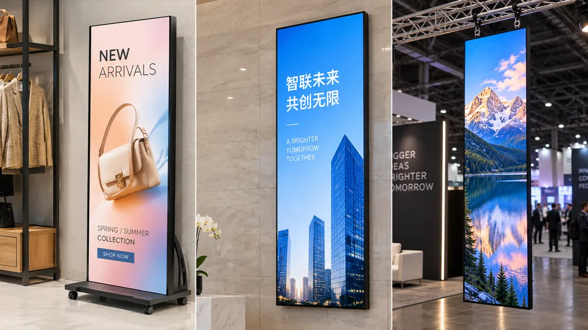
- Floor stand is the default starting point. 90% of LED poster deployments use a floor stand — it requires zero wall penetration, positions the poster at optimal eye height (center at ~1.5m), and supports cable concealment through the hollow pole. If you’re unsure which mounting method to use, start with the floor stand.
- The mounting plate bolt pattern is the spec that matters. Every poster model has a VESA or proprietary bolt pattern on the rear panel. If your floor stand mounting bracket doesn’t match the poster’s bolt spacing, you’ll need an adapter plate — and adapter plates introduce wobble. Always order the stand from the same manufacturer as the poster to guarantee pattern compatibility.
- Counterweight is not optional. A 50kg poster on a narrow floor stand base will tip if a shopping cart hits it. DOIT VISION floor stands ship with a 4-bolt base plate and a 15kg counterweight option. If the poster is in a public area, the counterweight is mandatory.
- Wall mounting requires knowing what’s behind the drywall. A P2.5 poster weighs 38kg — far beyond a standard TV mount. The wall plate must catch at least two structural studs or be anchored into concrete. Drywall anchors alone will fail within weeks.
What Actually Arrives — The Poster and Its Mounting Hardware
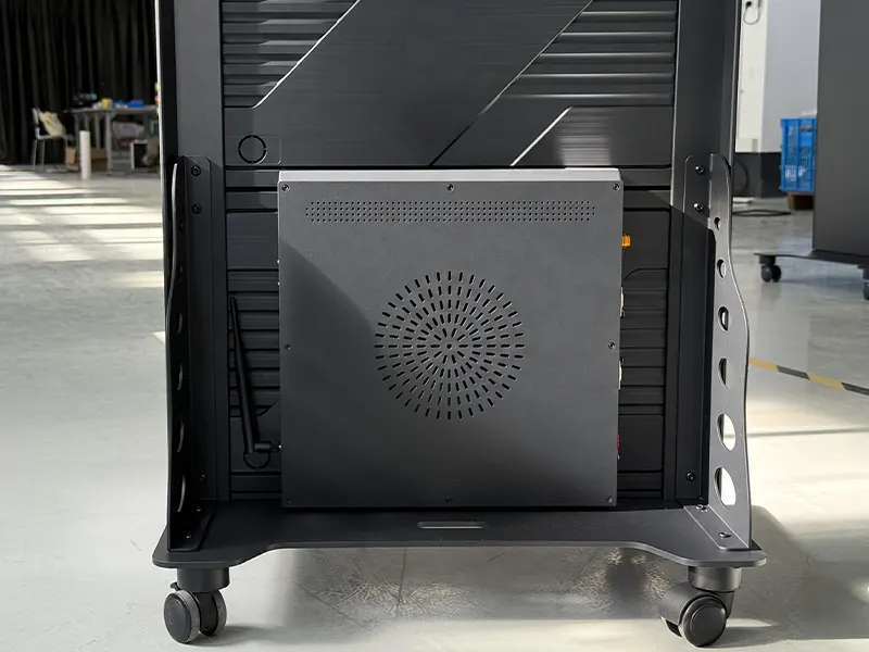
Before discussing installation methods, understand what you’ll have in hand. A DOIT VISION LED poster shipment contains:
| Bestanddeel | Notes |
|---|---|
| LED poster body (assembled) | Aluminum frame, pre-assembled modules. Weight 28–50kg depending on pixel pitch and size. |
| Floor stand (if ordered) | 3-piece steel pole + base plate + mounting bracket + hardware kit. Ships in a separate flat box. |
| Wall mount bracket (if ordered) | Steel wall plate + poster-side hooks. Lag bolts for wood studs NOT included — anchor type depends on wall material. |
| Novastar sending card + receiver | Pre-installed internally. Access via rear service panel. |
| Power cable (2m) + CAT5 signal cable (2m) | Standard IEC C13 power, RJ45 for NovaLCT control. Longer cables available as accessory. |
| Flight case (optional) | Custom foam-cut interior. Rental fleets: order flight cases. Fixed installations: skip them, save $200–$400. |
| USB drive with NovaLCT software + configuration file | Contains the .rcfg file pre-loaded with your poster’s module arrangement. Do not lose this USB. |
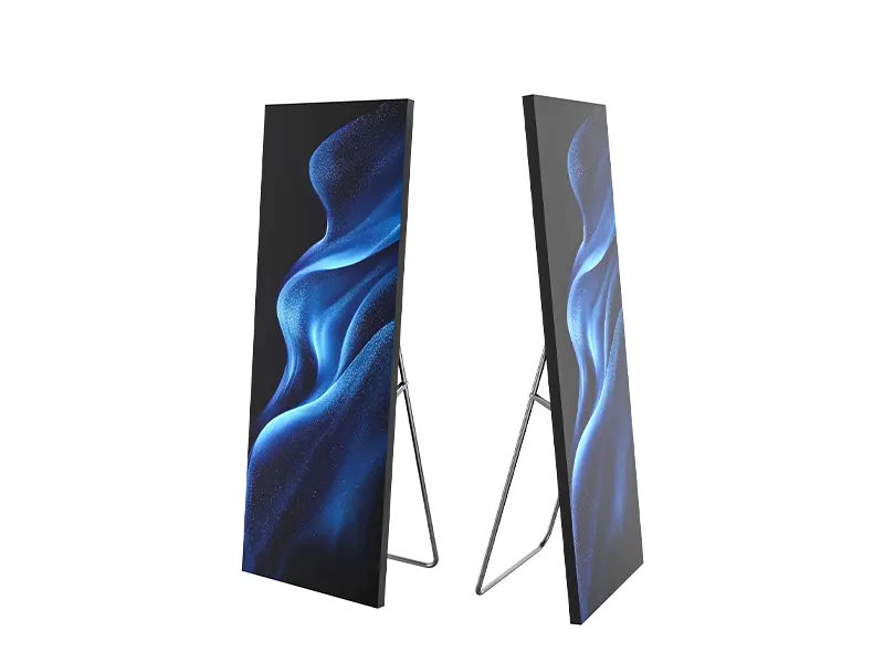
Open the flight case or carton and photograph the poster from all four sides before removing any protective film or packaging. If there’s shipping damage, the carrier requires photos with packaging intact. Once you’ve removed the foam and peeled the film, a shipping damage claim becomes significantly harder to win. This applies especially to COB posters — the surface itself won’t scratch, but the aluminum frame can dent if the box was dropped.
Floor Stand Installation — Step-by-Step With Dimensions

The floor stand is the most common LED poster mounting method for good reasons: zero wall damage, portability, and a 10-minute setup time once you’ve done it once. Here’s the assembly sequence with the dimensions that matter.
Stap 1: Monteer de basis
The floor stand ships as three components: a steel base plate (typically 600×450mm, 8mm thick), two or three hollow steel pole sections that screw together (total height 1800–2000mm), and a mounting head bracket that attaches to the poster’s rear VESA plate. Start with the base.
Place the base plate on the floor. Thread the lowest pole section into the center thread on the base plate. Hand-tighten, then use the included hex wrench for a half-turn past hand-tight. Do not use power tools — the threads are M10 coarse pitch and strip easily under impact driver torque.
tegengewicht: if your poster is going into a public area, bolt the 15kg steel plate (sold as accessory) to the underside of the base before attaching it. A poster on a narrow stand has a high center of gravity. The counterweight reduces the tip angle from ~12° to ~5° under a 50N lateral force — the difference between a poster that wobbles and one that goes over.
Step 2: Assemble the Pole
Screw the middle pole section into the base pole. Then screw the top section (with the mounting head bracket) into the middle section. The total assembled height should place the poster center at approximately 1.5m from the floor — the optimal viewing height for a standing adult audience. If the poster is 2000mm tall, the bottom edge will sit approximately 500mm from the floor.
Step 3: Attach the Poster
This is the step that requires two people. The poster’s rear panel has a steel mounting plate with M8 threaded holes in a rectangular pattern. The pattern varies by model:
| Poster Model | Bolt Pattern (W×H) | Bout grootte | Maximale hoogte |
|---|---|---|---|
| Standard sizes (640×1920mm) | 400 × 600mm | M8 | 1980mm (pole fully extended) |
| Foldable poster (600×2025mm) | 400 × 800mm | M8 | 2100mm |
| Large format (960×2560mm) | 600 × 1000mm | M10 | 2600mm (reinforced base required) |
With two people, lift the poster and align the rear mounting plate holes with the bracket bolts. One person holds the poster while the other threads all four M8 bolts finger-tight, then tightens them evenly in a cross pattern with a 13mm socket or the included hex key. Torque spec: 15–18Nm. Overtightening warps the aluminum frame.
Step 4: Level and Test Stability
Use the adjustable feet on the base plate to level the poster on uneven floors. Push gently on the top of the poster — it should rock no more than 3–5mm and return to center. If it rocks more or stays tilted, tighten the pole connections and check that the base plate is flush with the floor. If on carpet, the base plate feet may sink — place a rigid steel plate or plywood sheet under the stand to distribute the load.
Mark the pole sections with colored electrical tape at the correct insertion depth. When you’re setting up 8 posters in a 45-minute load-in window, the tape marks mean you don’t have to measure anything — just tighten until the tape line disappears into the joint. One small piece of tape per pole saves 2–3 minutes per poster setup.
Wall Mount Installation — What’s Behind the Wall Decides Everything

Wall mounting saves floor space and creates a cleaner, more permanent look. It also introduces structural questions that the floor stand avoids entirely. The poster weighs 28–50kg depending on model. A 55-inch consumer TV weighs 15kg. The poster is 2–3 times heavier than the heaviest TV you’ve ever wall-mounted. Behandel het dienovereenkomstig.
Wall Type and Anchor Selection
| Wall Type | Anker | Aantal | Notes |
|---|---|---|---|
| Wood stud (16″ OC) | M8 lag bolts, 75mm | 4 bolts into 2 studs | Pilot hole required at 70% of bolt diameter. Stud finder mandatory. |
| Beton / baksteen | M10 wedge anchors or sleeve anchors | 4–6 anchors | Drill depth must exceed anchor length by 10mm for dust clearance. |
| Steel stud (commercial) | Toggle bolts through steel | 6+ toggle bolts | Steel studs alone are NOT rated for 50kg. Add ¾” plywood backer spanning 3 studs first. |
| Drywall only (no studs) | DO NOT MOUNT | - | Drywall anchors of any type will fail under 50kg. Open the wall and install blocking between studs, or use a floor stand. |
Montage hoogte
The optimal center height for an LED poster in a retail or lobby environment is 1.5m from the floor — the eye line of a standing adult. For wall mounting, subtract half the poster height to find the bottom edge position:
- 640×1920mm poster → bottom edge at 540mm from floor
- Standard 600×2025mm foldable → bottom edge at 487mm from floor
- 960×2560mm poster → bottom edge at 220mm from floor (lower, given the larger viewing distance)
Also consider what’s below the poster. In a retail setting, a poster with bottom edge at 540mm above floor level means the display surface starts above the knee — safe from shopping carts and vacuum cleaners. In a corporate lobby, you might go lower if the poster serves a seated waiting area (reduce center height to 1.2m).
Every poster ships with a CAD drawing. If yours is missing or you’re planning the installation before ordering, ask an engineer for the mechanical drawing — it shows bolt positions, service panel location, and cable exit points.
Truss Mount and Rigging — Exhibition Booths, Concert Stages, Event Production
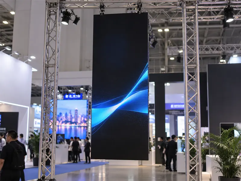
When the poster is going into a temporary structure — an exhibition booth, a concert stage backdrop, a conference keynote setup — the floor stand is often too low and the wall doesn’t exist. Truss mounting is the solution, and it introduces safety considerations that don’t apply to floor-standing installations.
Truss Mount Hardware
LED posters mount to standard aluminum box truss (290mm or 390mm square) using a truss clamp adapter. The adapter consists of:
- A half-coupler or trigger clamp rated for 250kg SWL (safe working load) that wraps around the truss chord (48–51mm diameter)
- A vertical mounting bar (steel, 40×5mm flat bar) that drops from the clamp and bolts to the poster’s rear mounting plate
- A safety cable (steel wire rope, 4mm diameter, 500kg breaking strength) as a secondary attachment — threaded through the poster’s safety point and around the truss chord
Single vs Dual Clamp
A poster hung from a single clamp will rotate if bumped or if there’s airflow from HVAC. For exhibition booths where the poster is a backdrop — not moving, no touching — a single clamp is sufficient. For concert stages, outdoor events, or anywhere the poster might be walked past, use two clamps spaced 600–800mm apart on the same horizontal truss chord. Two clamps prevent rotation and distribute the load.
For posters wider than 960mm, two independent vertical mounting bars are recommended — one at each side of the poster frame. This prevents the poster from twisting along the vertical axis, which single-center mounting can allow even with dual clamps.
Safety Cable — Not Optional
Every poster has at least one safety attachment point — a reinforced mounting hole or eyebolt — on the top edge of the frame. When truss-mounting, a steel safety cable must run from this point to an independent truss chord, not the same chord the clamp is attached to. The reason: if the clamp fails (extremely unlikely at 250kg SWL for a 50kg poster, but safety protocols exist for a reason), the poster falls until the safety cable catches it — approximately 200mm. Without the safety cable, it falls to the ground. At an exhibition, that means a destroyed $3,000 poster plus liability for whatever or whoever it lands on.
Most European exhibition halls (Messe Frankfurt, Fira Barcelona, RAI Amsterdam) require a structural engineer’s sign-off for any rigged load exceeding 100kg. A single LED poster is 28–50kg — well under the threshold. But if you’re hanging multiple posters from a single truss or combining posters with lighting fixtures, the total load can exceed 100kg. Check the exhibition technical manual — it will state the hall’s rigging point capacities and the documentation required for loads above a certain threshold. Getting this wrong means the hall’s technical team will ask you to take it down, and they’ll be right to do so.
Ceiling Hanging — When the Poster Needs to Float
Ceiling-hung LED posters are uncommon but essential in two scenarios: retail spaces where floor space is at an absolute premium (duty-free shops, jewelry counters, narrow aisles), and double-sided poster installations where the poster serves as a hanging directional sign visible from both sides.
Ceiling Anchor Requirements
The structural requirement here is straightforward but non-negotiable: the ceiling anchor point must be rated for 5× the poster weight — so 140–250kg for a 28–50kg poster. This factor of safety accounts for dynamic loads (the poster swinging if bumped), plus the fact that a ceiling fixture failure is more dangerous than a floor stand tip-over.
Acceptable anchor points:
- Structural steel I-beam or girder — beam clamp rated for the load. 15-minute installation with no penetration.
- Concrete ceiling slab — M12 through-bolt or wedge anchor, minimum embedment 80mm. Drill into the slab, not into a ceiling tile grid.
- Wood joist (residential/commercial timber frame) — M10 lag bolt through ceiling drywall into joist. Joist must be confirmed with a stud finder and pilot-drilled to verify it’s structural, not strapping.
Unacceptable: ceiling grid wire, threaded rod through a ceiling tile T-bar, any attachment to HVAC ductwork, or anything that was not designed to carry load. Ceiling tiles and their suspension grids are rated for their own weight plus light fixtures — typically 5–10kg per point — and nothing more.
Cable Drop Installation
The poster hangs from two steel cables (aircraft cable, 3mm diameter, 7×19 strand construction for flexibility) attached to the top edge of the poster frame. Each cable runs from a threaded eyebolt on the poster, up to a Gripple or turnbuckle attached to the ceiling anchor, with length adjusted so the poster hangs level. The bottom edge of the poster should be at minimum 2.1m above floor level — this provides head clearance for the tallest expected person and is the standard minimum height for any overhead fixture in public spaces per most building codes.
A double-sided hanging poster has LED modules on both faces. It’s approximately 1.5× heavier than a single-sided poster of the same size. The ceiling anchor rating must account for this, and the poster frame needs a center-mounted hanging point with reinforcement plate — if you hang a double-sided poster from two edge points, the frame will twist under its own weight and the seam between the two faces will open up. DOIT VISION double-sided posters have the center hanging point as standard; third-party frames may not.
Cable Management and Power — Make It Look Like There Are No Cables
A beautiful LED poster with dangling wires looks like a prototype. Cable management is not cosmetic — it’s the difference between a professional AV installation and a trade show demo that didn’t finish on time.
Floor Stand Cables
The floor stand pole is hollow steel — the power and signal cables should run inside the pole. Feed the cables from the poster’s rear service panel down through the top opening of the pole, out through a slot near the base plate. The DOIT VISION floor stand has a 20mm cable exit slot at the base — the two cables (power + CAT5) fit comfortably. From the slot, run the cables along the floor to the nearest outlet, secured with gaffer tape or a low-profile floor cable cover in public areas.
Do not use cable ties around the outside of the floor stand pole. It looks temporary and the ties collect dust. Internal routing through the hollow pole takes 30 extra seconds during setup and looks permanent.
Wall Mount Cables
Wall-mounted posters need a power outlet within 1.5m of the poster’s bottom edge. The outlet should be directly behind or immediately below the poster — if the cable has to run sideways along the wall, it will be visible. For new construction or serious retail renovation, install a recessed outlet box directly behind the poster mounting plate. The poster covers it completely, and zero cable is visible.
For existing spaces where cutting into the wall is not an option, run the cables in a paintable surface-mounted raceway. Paint the raceway to match the wall color — a white raceway on a beige wall draws the eye more than the poster does, which defeats the purpose. Raceway cost: $15 for a 2m channel at any hardware store. Alternative: a $150 electrician to fish the cable through the wall. Both are acceptable; visible cables are not.
Stroomvoorziening
A standard LED poster draws 300–600W depending on size and pixel pitch. This is well within a standard 15A / 110V circuit (or 13A / 230V in Europe). However, if you’re installing multiple posters on the same circuit, add up the maximum power draw — not the typical draw — and leave 20% headroom. A P2.5 poster at max brightness (white screen) draws approximately 450W. Four posters on one circuit = 1800W. A 15A circuit at 110V provides 1650W max (1650 × 0.8 = 1320W safe continuous). Four posters on one 15A circuit = trip the breaker during startup when all four power on simultaneously. Distribute across circuits or stagger power-on.
The 5 Most Common Setup Mistakes That Cause Service Calls
These are the installation errors we see in service reports most frequently. Each one is avoidable.
Mistake 1: Not Locking the Pole Sections
The two floor stand pole sections screw together with M10 threads and include a locking collar — a knurled ring that tightens against the joint to prevent rotation. The collar must be tightened after the sections are assembled. If it’s not, vibration from foot traffic will gradually unscrew the pole sections, and the poster will slowly rotate. In a retail store with heavy foot traffic, this takes 2–3 days. Tighten the locking collar. Then check it again before you leave the site.
Mistake 2: Wall-Mounting Without Checking Stud Spacing
The poster’s wall mounting bracket spans approximately 500mm horizontally. Standard wood stud spacing in North America is 16 inches (406mm) on center. The bracket’s bolt holes must align with two adjacent studs. If they don’t, you need a mounting plate that spans the bracket width and bolts into the studs wherever they are, then the bracket bolts to the plate. Measure stud spacing before ordering the mount. If your studs are at irregular spacing (common in older buildings), order a universal mounting plate rather than drilling new holes in the poster bracket.
Mistake 3: The CAT5 Cable That’s Not CAT5
The poster’s Novastar sending card connects to the control PC via Ethernet — specifically a CAT5e or CAT6 cable with RJ45 connectors. Wi-Fi is not an option for show-critical content; the poster needs a wired connection for reliable signal. The mistake: using a cheap “comes with the router” cable that’s actually CAT3 or unshielded CAT5 with molded strain relief that breaks after two insertions. Use a shielded CAT6 patch cable — cost is $8, signal integrity over 50m is perfect, and the molded boot won’t crack when you unplug it at the end of a show.
Mistake 4: Forgetting the Spare Module
If you’re setting up for a trade show, exhibition, or any event where a dead pixel would be noticed, carry one spare LED module in the flight case. A module replacement on a poster takes 7 minutes — four screws, disconnect one ribbon cable, swap, reconnect, re-screw. The alternative: a dead pixel visible for the entire 3-day show, with every attendee who walks past seeing a black dot on your brand content. A spare module costs $40–$80. Bring it and you won’t need it. Don’t bring it and the one module that fails will be the center module at eye height.
Mistake 5: Running the Poster Without Configuring NovaLCT
The poster arrives from the factory pre-configured — the Novastar receiving card has the correct module arrangement file (.rcfg) loaded. But if the poster is reset, if the sending card is swapped, or if you’re connecting a poster from a different batch, the configuration must be reloaded. The symptom: the poster displays content but the image is scrambled — wrong module order, incorrect resolution, garbage on half the screen. The fix: open NovaLCT on the control PC, connect to the sending card, load the .rcfg file from the USB drive that shipped with the poster. This takes 3 minutes and restores the factory configuration. Keep the USB drive labeled with the poster’s serial number in the flight case.
Glass walls, historic buildings, sloped floors, outdoor covered areas — send photos of the space and we’ll recommend the right mount or design a custom bracket.